
This tutorial was inspired by one of the most
important buildings in Saudi Arabia.The
cladding system is made up of rhomboid
textile awnings, marked by its play with revealing and concealing. Inserted white membranes, supported by a
three-dimensional, tensile-stressed steel
cable structure, act as sunshades and interpret the Arabian tent structure
tradition in a modern, technological
way. (See below image)

Photo Source ArchDaily
01. In the Applications menu, go to New >
Family, select "Curtain Panel Pattern Based" and click Ok. Select the blue grid in the
background, and click on the Type Selector and change the grid type to "Rhomboid".
Save As the family and proceed. Select the blue grid again, in the properties
menu, change the Horizontal Spacing to 3000 and the Vertical Spacing to 4000. (See below image)

02. Place a single reference point on the xy-plane of the adaptive points no. 1, 2 and 3. Select the three points highlighted below with red circles; change the Offset of the three points to 2500 so that they all elevate at the same height.

02. Place a single reference point on the xy-plane of the adaptive points no. 1, 2 and 3. Select the three points highlighted below with red circles; change the Offset of the three points to 2500 so that they all elevate at the same height.

03. Select the two new points together. (For multiple selections, click on the new points one after the other while holding down the Ctrl button).
In the Properties Menu, click the small button
to the right of "Offset" (See below red arrow).
The
"Associate Family Parameter" will open. Click on "Add
Parameter", make a new Type Parameter,
call it "PANEL DEPTH" and click ok to close the windows.This
parameter will be used control the simultaneous vertical movement of the
selected points, and will dictate
the depth of the panel.

04. Create three new reference lines as
highlighted in the below image. Each
Reference line connects an adaptive point with the reference point above it
leaving out adaptive point number
4.

05. Create two new reference lines through the
three reference points created earlier. (See
below image)


06. Create two new mid points on the new reference
lines from the previous step. To
confirm the centralization of the points, the Normalized Curve Parameter should
read 0.5 (See
below image).

07. Create two new mid points on the reference
lines between adaptive points no. 1, 4 and 3.
To
confirm the centralization of the points, the Normalized Curve Parameter should
read 0.5 (See
below image).


08. Go to the midpoint hosted on the reference
line between adaptive points no. 3 and 4. Place
a point on the vertical plane (highlighted below in yellow) of the midpoint.
Ignore the error that appears by
clicking "Ok". Select the point and drag it inwards (follow the red
vector below).

Select the new point and repeat the procedure
in step 2.6 above but the name the Instance Parameter "AUTO_RADIUS".

09. Multiple select adaptive points no. 4 and 3 in addition to the new point
from the previous step then click
"Spline Through Points". This will create an arch between the
selected points. In the Properties Menu,
check "Is Reference Line". (See below image)


10. Repeat steps 2.11 to 2.14 so that your geometry
resembles the below image.


11. Next we need to create a Reporting Parameter. In order to do so, type
"DI" to activate the Aligned
Dimension command, click on "Set" to assign a work-plane and click on
the vertical plane of Adaptive point no.
2. (See below sketch)


12. To apply the dimension, click the two reference planes of Adaptive Points
no. 2 and 4 highlighted below in
blue one after the other. (See below image)

13. Select the dimension, click the "Label" drop down and select
"<Add parameter>", name the new
Instance Parameter "Panel Height" and check "Reporting
Parameter" then click "Ok". (See below image)

14. In the next step, we will create the central part of the panel that will
host fabric connection. (See below image)

Photo Source ArchDaily
15. Draw a reference line between adaptive points no. 2 and 4. (See below
image)

16. Isolate the central line witn the adaptive points
bounding it from either side. (See below image)

17. Now host 4 no. ref. points with Normalized Curve
Parameters as indicated in the below image.

18. Now we will host a point on top of each normalized point
from the previous step except the point
marked in blue.
Move the points slightly upwards.
Move the points slightly upwards.
Note: The points should be
hosted on the xy-plane (marked in yellow) of the normalized points. (See
below image)

19. Open up the Family Types Editor where you will see all the parameters that you have created.

20. Under the Formula section, replicate the below data in order to achieve parametric control.

21. Create a "Spline Through Points" starting from Adaptive point no. 4 as displayed below.

22. Orbit your geometry so that Adaptive point no. 2 is situated to the left of the background.
Isolate Adaptive points nos. 2, 3 and 4 in addition to all lines and
points connecting these three points. Then add hosted points with Normalized Curve Parameters as represented in the
below image.

23. Sketch a "Spline Through Points" following
the "x" symbol and skip the two
points marked as "Skip point". (Refer to below image)

24. Repeat the previous step on the opposite side
connecting Adaptive points no. 2, 1 and 4.
Select the two splines marked by a red arrow in the
below image.

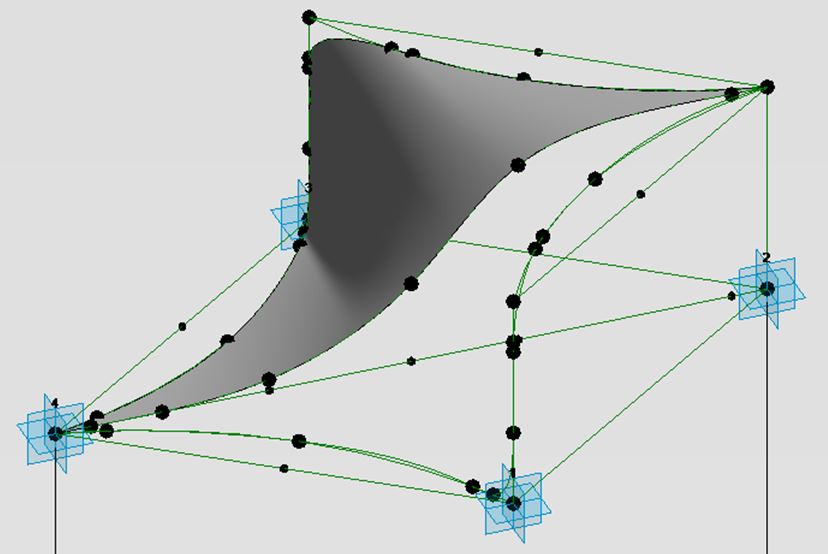
25. Create a surface between the two splines from the
previous step. (See below image)
26. Repeat the previous two steps from above to complete
the panel. (See below end-result)

27. Create a mass family, use Rhomboid divisions and apply
the Final Panel. (See below image)


Note: See below images.

Above image is taken from Revit.

Actual Elevation Photo Sourced from ArchDaily
Congratulations!
You have completed this tutorial.